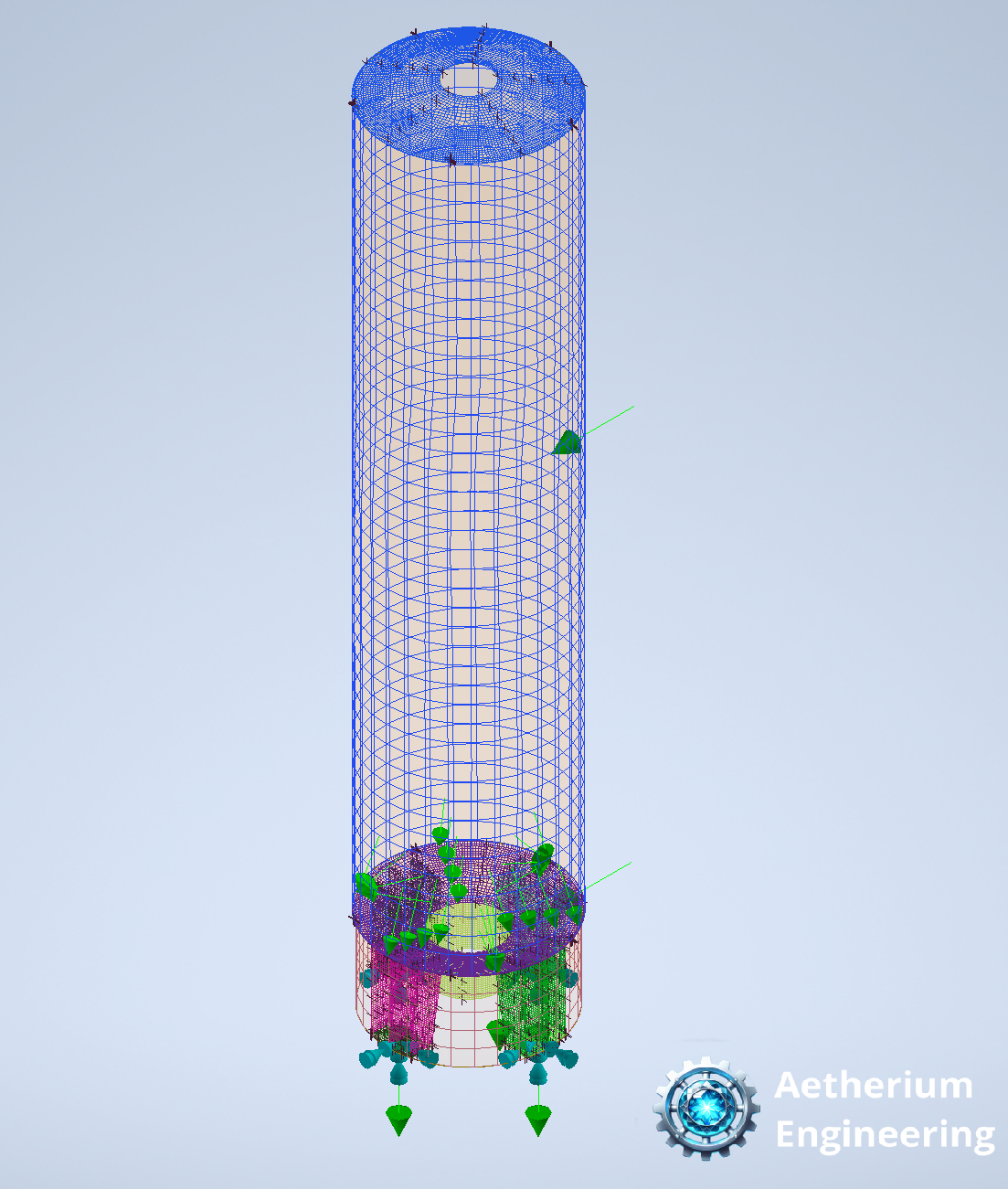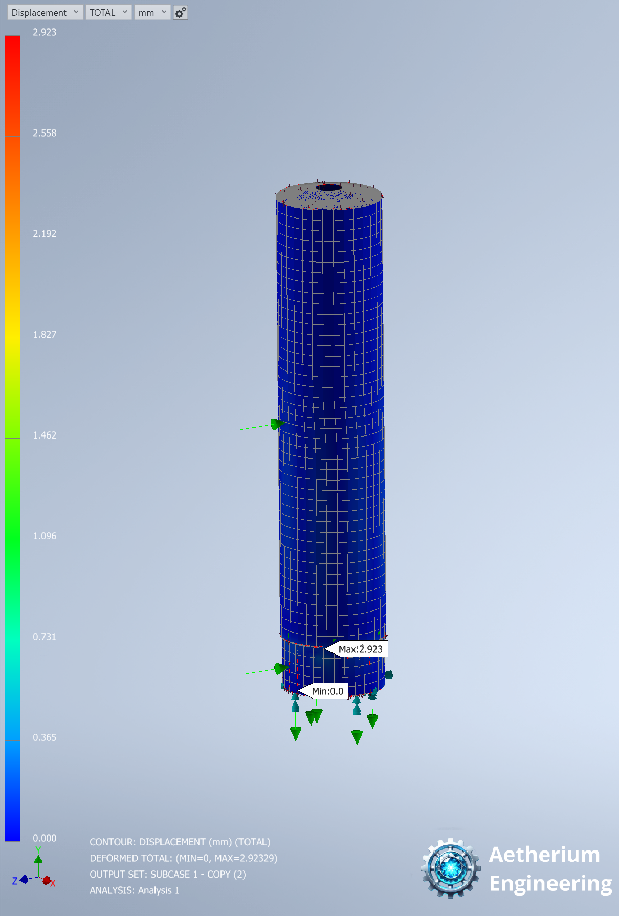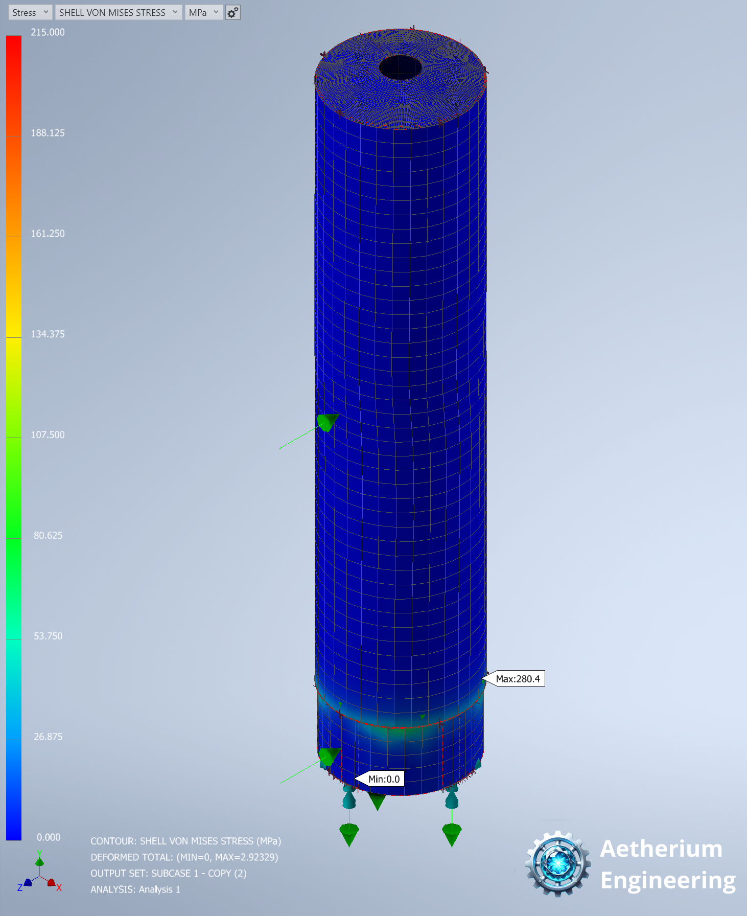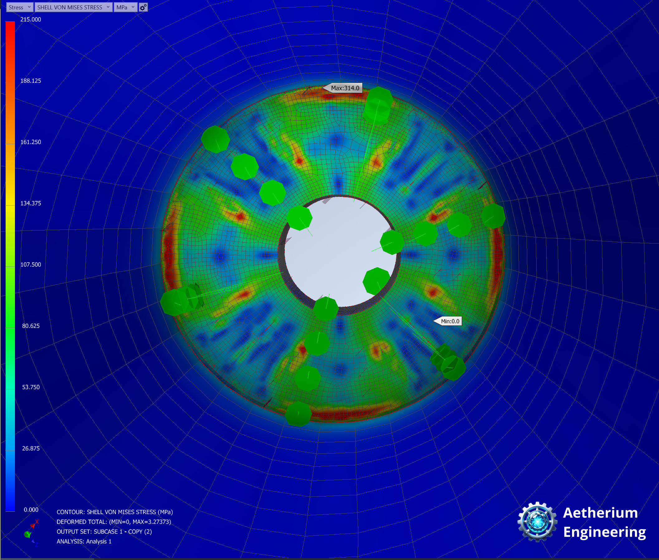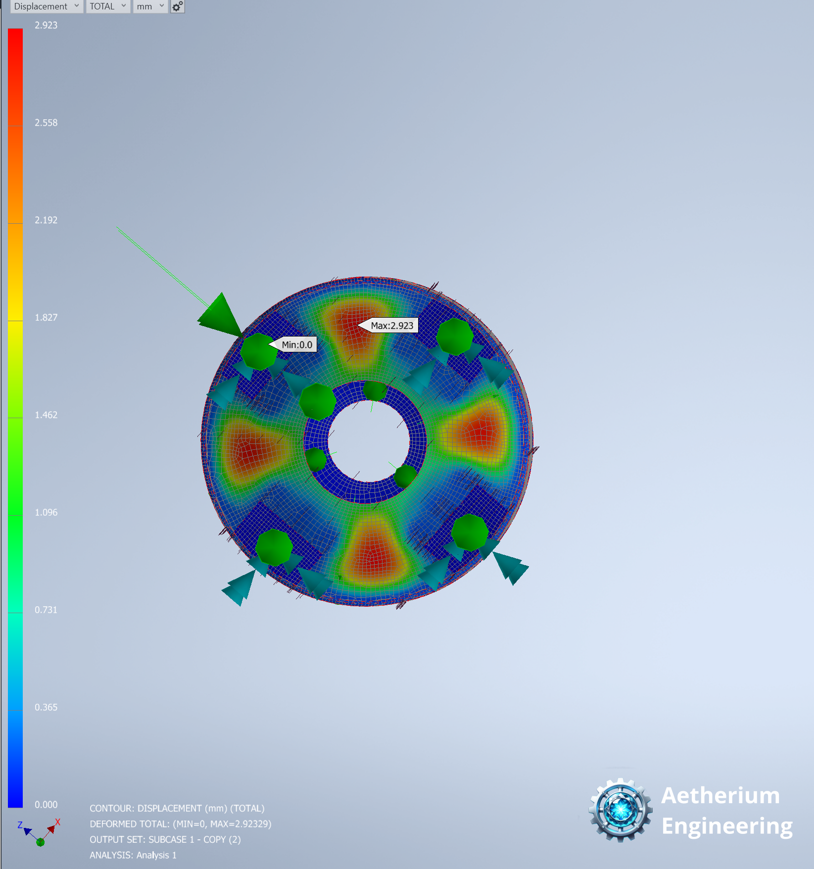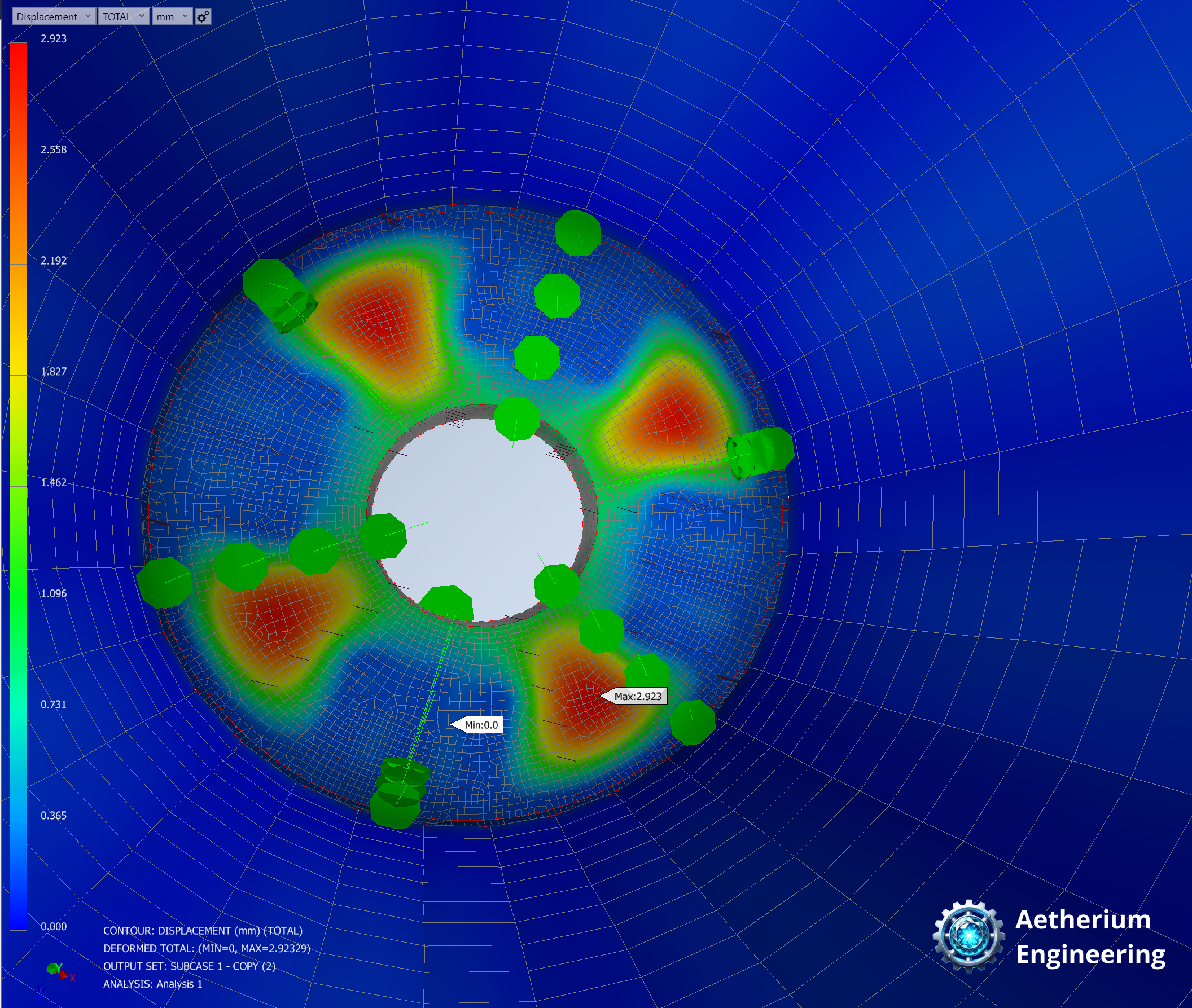
A Finite Element Analysis (FEA) was carried out on a vertical process vessel to assess its structural integrity under realistic service conditions. The analysis was performed using Autodesk Inventor Nastran to evaluate global behaviour, support conditions, and stress distribution under combined operational loads.
The study provided confidence in the vessel’s overall performance while identifying localised areas requiring further engineering consideration.
Vessel Description
The vessel assembly consisted of:
- Top cone
- Main cylindrical shell
- Bottom dished end
- Skirt support with four legs
- Heat exchanger attached at the bottom nozzle
The vessel was modelled in a vertical orientation and supported on a structural frame, which was included in the analysis to capture the effect of frame flexibility on vessel behaviour.
Analysis Assumptions
To ensure a realistic but efficient simulation, the following assumptions were applied:
- Materials were assumed homogeneous and isotropic
- Thermal effects were excluded, as temperature-related stresses were not considered critical for this service condition
- Loads were applied as static, with no dynamic or fatigue effects considered
- Welded connections were assumed to be full-penetration, providing full load transfer
These assumptions are appropriate for assessing global structural performance under service loading.
Model Simplifications
To maintain computational efficiency without compromising accuracy:
- Minor fittings such as small nozzles, lugs, and stiffeners were not explicitly modelled
- The heat exchanger was represented as an equivalent point load applied at the nozzle flange
- No safety factors were applied to input loads, as the analysis focused on in-service conditions rather than code verification
Material & Idealisation
- Material: Stainless Steel AISI 304
- The vessel was idealised primarily using shell elements, derived from mid-surface geometry
- This approach provided accurate stress representation for thin-walled components while controlling model size
Boundary Conditions & Contacts
- The vessel was fixed at four legs at the base
- Surface-to-surface contacts were applied between the vessel skirt feet and the supporting frame
- Edge-to-surface contacts were used at shell-to-dish transitions and shell junctions
- All contacts were defined as bonded, representing welded connections with no slip or separation
- Adaptive stiffness scaling was enabled to improve contact stability
Meshing Strategy
- Parabolic (second-order) elements were used to improve stress and displacement accuracy
- A global element size of 200 mm was applied to capture global behaviour efficiently
- Local mesh refinement to 20 mm was introduced at areas of expected stress concentration, such as dish knuckles and shell transitions
Mesh quality warnings were reviewed and assessed. Isolated element distortions were accepted where they did not affect critical stress regions or global response. Geometry-related meshing issues were resolved through parameter adjustments within the geometry processor.
Loading Conditions
The following loads were applied in accordance with EN 1990 and EN 1991-4:
- Self-weight applied through individual leg reactions
- Hydrostatic pressure acting on the bottom dish and vessel shell
- Equipment load from the attached heat exchanger
- Wind load applied to the shell and skirt
Analysis Type
A linear static analysis was performed to evaluate vessel integrity under combined service loads.
Buckling, fatigue, and thermal assessments were not included at this stage.
Results & Findings
The analysis confirmed that:
- Global stresses remained within allowable limits for the applied load cases
- Overall vessel behaviour was stable, with acceptable displacement levels
- Localised high stresses were observed at:
- The inner leg-to-dish interface (local and non-critical)
- The bottom dish knuckle region, likely driven by geometric stress concentration
While these stresses were local in nature, the bottom dish knuckle area was identified as requiring further investigation, potentially through local reinforcement, geometry optimisation, or refined sub-modelling.
Outcome & Value
The FEA provided:
- Validation of the vessel’s structural integrity under realistic service conditions
- Improved understanding of load transfer through the skirt, legs, and support frame
- Insight into the influence of support frame flexibility on vessel stresses
- Clear engineering evidence to support design decisions and potential improvements
This study demonstrates how targeted FEA can be used not only to confirm compliance, but also to guide smarter, more resilient design outcomes.